Separable Fastening Device

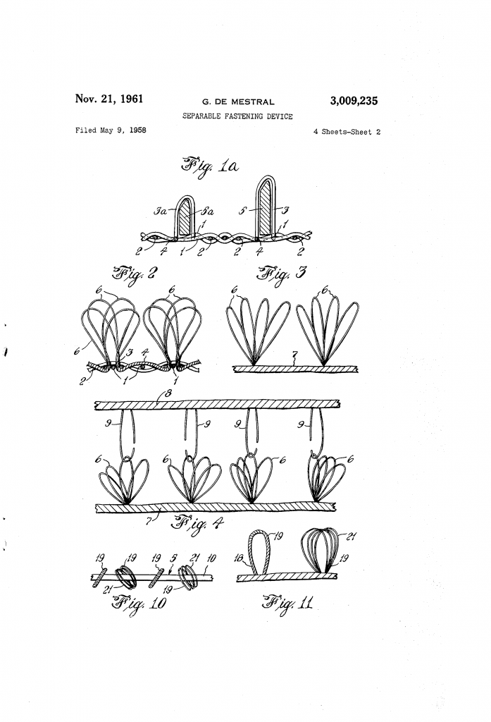
Who would have thought that burs from a Burdock plant could spark a new idea for an innovation that is still used worldwide today? Putting a Burdock plant under a microscope to figure out how the tiny hooks on the burs attached by themselves is exactly what George de Mestral was fascinated by. He then imitated the burs’ structure to generate a synthetic fastening system. De Mestral was the first person to invent the separable fastening device that was filed as a patent for something to be attached together with a strong bond. Or, as we know it today: Velcro.

George de Mestral was a Swiss engineer whose idea for Velcro all started when he was on a hunting trip in 1941. While on the hunting trip, his pants and his dog’s fur became coated in burs from a Burdock plant. Instead of just trying to remove the burs, he wanted to learn how they attached and studied them under a microscope.

Underneath the microscope, de Mestral saw “thousands of tiny hooks that efficiently bound themselves to nearly any fabric (or dog hair) that passed by.”[i] He came to understand that he could generate a synthetic form of this specific method, which would be an innovative way to secure things together. His idea was to combine hooks similar to those in the burs with loops of fabric. The hooks would latch onto the loops, creating something that would connect and attach together but also be removable, a possible substitute for other connectors such as buttons or zippers.

While realizing that the tiny hooks in the burs were a complex concept to understand, de Mestral took a tour in Europe of fabric manufacturing plants. The loops of fabric were simple to produce, but the tiny hooks were more challenging. The hooks “needed to be both flexible enough to separate from the loops when pressure was applied, yet firm enough to keep things together otherwise.”[i]

Fortunately, there was a manufacturer in Lyon, France that was merging strong nylon with cotton. De Mestral used a velvet-type material to put the hooks in by hand, applied heat to keep them firm, and then connected it with a piece of cloth that had tiny loops. He found that the loop side needed far more loops per area than the hook side, so that the greatest possible number of hooks would engage. After creating this separable fastening device, he received a patent in 1961, along with creating a new company he named the International Velcro Company.

George De Mestral’s innovation was not popular at first because people had no idea what it was to be used for or even how it was to be used. Eventually, however, the National Aeronautics and Space Administration came into play. The agency needed a way to stop objects from floating around while in zero gravity and found that Velcro was the solution. Because of NASA, Velcro officially started becoming more successful. His creation started showing up especially in the clothing and fashion industry.

De Mestral, however, was an inventor at heart and sold the rights to his separable fastening device to the Velcro Company, so that he could spend the rest of his life working on other inventions. He passed away in 1990 but will forever be recognized as the one who first created the separable fastener device we know as Velcro. And even though the innovative patent terminated in 1978, Velcro is still a trademarked term.

 By Stephanie Lew


[i] Jake Swearingen. (2016, November 11). An Idea That Stuck: How George De Mestral invented The Velcro Fastener. Retrieved February 6, 2018, from Velcro: https://nymag.com/vindicated/2016/11/an-idea-that-stuck-how-george-de-mestral-invented-velcro.html

Wireless Network Assisted GPS System

The power to explore and navigate throughout the known world and beyond was once restricted to mythological heroes or those of extraordinary ability. When the U.S. was in an arms race with Russia during the Cold War, the U.S. strove to gain an edge in the competition through technological superiority. In doing so the United States would push their scientists and resources to harness the ability of geolocation through innovative technologies. Before the 20th century, navigation required a suite of tools and skills taking many years to master: the ability to chart the movements of the stars, sun, and moon; access to maps, compasses, and local knowledge; or the use of landmarks, natural signs, and deduction were the most efficient tools for navigation in the United States. Space age technology in the form of the Global Positioning System (GPS) presented a transformational change to society by allowing untrained individuals to perfectly assess their location with a single piece of equipment. Then the 2007 invention of a Wireless Network Assisted GPS System improved upon the use of GPS.

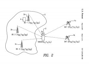
The Wireless Network Assisted GPS System is described in its patent abstract as “A method and apparatus for locating a mobile communications device such as a cell phone includes apparatus for communicating with base stations and apparatus for communicating with satellites. Signals received from satellites and the base stations are combined to provide the necessary information to calculate the location of the mobile communications device.” The Wireless Network Assisted GPS System is specifically tied to a mobile communications device such as a cell phone. This innovative technology is dependent on NASA’s initiative that released numerous satellites into Earth’s orbit during the Cold War. This was an effort to extend the eyes and ears of the State Department and Department of Defense. These satellites would later become the backbone of most telecommunication technologies and industries in America. The maturation of satellite technology in this period would facilitate the development of the GPS satellite constellation.[i]

Today, most people regard the term GPS as a receiver device. Yet, GPS is a space-based navigation system composed of over two dozen different satellites perpetually orbiting the earth. The GPS receiver’s job is to communicate with the satellites to deduce its location by determining the distance from multiple satellites and the mobile unit as assisted by a wireless network, such as the Wireless Network Assisted GPS System. Determining the distance to different satellites with a known position allows for the location of the receiver to be deduced by triangulation. Timing is important to this process because distance is determined by the travel time of the signal.

The Wireless Network Assisted GPS System is a non-obvious utility to one reasonably skilled in the art, making it qualified to receive a patent. The patent is for a hybrid GPS system technology, where the position of a mobile unit is estimated using an existing wireless network. Inventor Sirin Tekinay (formerly Associate Professor in the Electrical and Computer Engineering Department at the New Jersey Institute of Technology) and her PhD student, Woo-Jin Choi, created an innovative geolocation technology resolving timing errors, effectively detecting GPS signals, and resolving power consumption issues. Differential GPS technology helps resolve timing errors via a “stationary reference receiver, which uses its known position to calculate timing” (US7215281B2). But Tekinay and Choi’s wireless innovation more effectively detects GPS signals and, by acting as a ground based relay, has solved or minimized the problems that occur in blocked connections from satellites to receivers.

Sirin Tekinay, Woo-Jin Choi, US7215281B2

Cited in patent continuity is the “GPS receiver utilizing a communication link,” from 1998 (US5841396). This GPS receiver was one of the earliest inventions involving GPS technology. Much of the science is similar in these two patents, because the Wireless Network Assisted GPS system is using the technology offered by the GPS receiver utilizing a communication link. Yet, the novelty of the Wireless Network Assisted GPS System relates to a geolocation technology, specifically a hybrid GPS system in which positioning of a mobile unit is realized with the assistance of a wireless network. This resolved difficulties of battery consumption and signal acquisition by having the ground based wireless network perform the computations necessary to resolve timing errors and act as a stepping stone to identify the location of the GPS receiver.

By Zachary Valbrun, Nikolette Petteway, and Abhishek Bose


[i] Dunbar, Brian. “Global Positioning System History.” NASA, NASA, 5 May 2015, www.nasa.gov/directorates/heo/scan/communications/policy/GPS_History.html.

Fluidized Bed Systems and Methods Including Micro-Jet Flow

Fluidized Bed Systems and Methods Including Micro-Jet Flow is an invention that significantly improved the process of fluidization. Fluidization is a process where you take a mass of particles—like a pile of sand—and make it act like a fluid by shooting air into the pile. Robert Pfeffer, Jose A. Quevedo, and Juergen Flesch at NJIT invented this improvement to the fluidization process. Their patent was filed on November 9th, 2007 and granted on February 21st, 2012 as patent US8118243B2. Fluidization is an important process used in the production of many everyday objects including foods, automobile parts, energy, and pharmaceuticals.

Examining the previous work of the inventors provides context for their decision to pursue improvements to the fluidization process. Jose Quevedo, who received his PhD in Chemical Engineering from NJIT in 2008, worked with his advisor, Robert Pfeffer (now Professor Emeritus at NJIT), on most of his patent applications and grants, so the two seem to come as a package deal. They have patents in means of the creation, fluidization, and usage of nanoparticles, which tend to be smaller than a common flu virus (see: US7645327B2, US7658340B2, US7905433B2, US8550698B2, and US8632623B2). They collaborated on this and other patents with German-based chemical engineer, Juergen Flesch, who holds additional patents in the fields of powder metallurgy. His patents involve  applications of nano-agglomerates (agglomerates meaning “a mass of objects or a group”) in forms such as zirconium-hafnium oxide and silicon dioxide powders, which can be used in the creation of scientific tools, electronics or other metallic parts that require high precision (see: US7785560B2 and US8197791B2).

The patent consists of an augmentation to the existing fluidization systems and chambers in use at the time. The system of the patent consisted of: 1) a fluidization chamber, the fluidization chamber configured to house a volume of nanoparticles, the nanoparticles having a particle size of less than about 100 nm; 2) a source of a fluidizing medium communicating with the fluidization chamber, the fluidizing medium being directed in a first direction relative to the fluidization chamber and 3) at least one micro-jet nozzle for delivering gas in a direction opposite relative to the first direction defined by the fluidizing medium. Although it is important to note that this configuration was specifically for use with particles smaller than 100 nanometers, the patent summary states that the method is suitable for particles up to 30 microns in size.

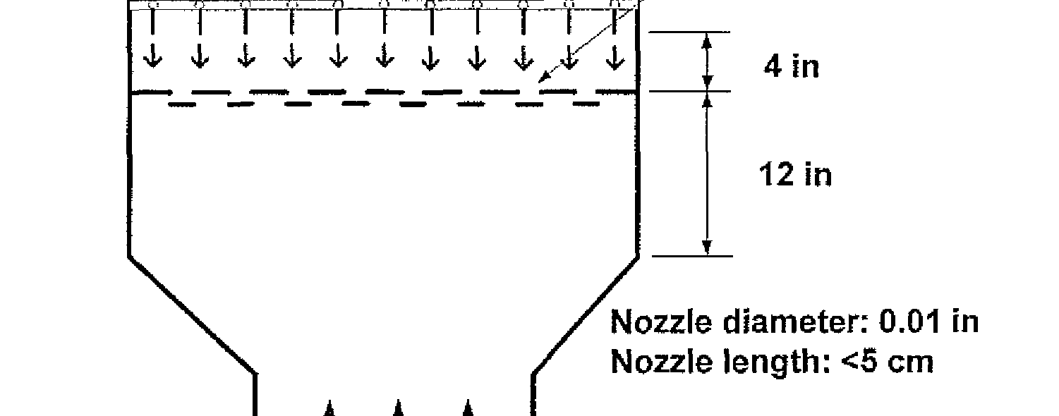
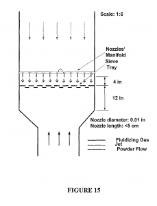
These opposite flow gas jets are the primary improvement to the fluidization process introduced by this patent. A ring with small nozzles is placed inches above the powder within the chamber. When air is forced upward through the particles and fluidizes them, the other nozzles fire downward in an exact opposite direction into the now fluid particles. The opposite direction flow creates vortexes, and this enhances fluidization and makes the mixture more uniform. Previously powders could clump together in “dead spots” around the chamber reducing the efficacy of the process.

Robert Pfeffer, Jose A. Quevedo, Juergen Flesch, US8118243B2

The fluidization technology already has been used in several fields, all of which can be enhanced by such an improvement. The fluidization model was first applied in 1922, when inventor Fritz Winkler created a carbon reactor with a process he called coal gasification. In this process fine grained coal is injected into a chamber where it is fluidized, then burned to heat a water chamber, producing steam, which then spins a turbine and creates electricity. This is far more efficient than simply burning the coal. With an improvement from the NJIT patent, it can reach very high efficiency, leaving nearly no residue in the process.[i]

As an example of application in the food industry, Nabisco foods has utilized a similar method wherein they use a chamber for powdered food storage (powdered sugar, cereal meals, flour, etc.), which then gets mashed down by a turning screw and then forced through a small hole to make cereal (see: US3729176A). A problem with this process is that larger particles liked to clump together and jam the screw. To fix this, they implemented a large, helical apparatus to lift the oats and other particles up, aerate them, and keep them from sticking together. A similar effect comes from our NJIT apparatus, which is much smaller—and likely far cheaper—to deploy.

Another method was invented as a means of reducing contaminants such as complex bound cyanide or polycyclic aromatic hydrocarbons (see: US4648332A). The values prescribed by safety commissions and in particular the Netherlands’ Chemical Waste Act are that of 5 parts per million and 0.1 ppm, respectively. Some regions can see close to 4000ppm and 3500 ppm for these contaminants, meaning the soil must be thoroughly cleansed. To do this, contaminated soil is introduced to a fluidized bed combustion chamber, like that of the Winkler process, and the large particles sink past the flames and are collected to be broken down and reintroduced. The lighter particles along with the contaminants rise and are burned away, leaving a product of clean soil and scrub-able, mostly harmless gases. If the soil could be more efficiently fluidized, then it would require fewer passes for all of the soil to be burned through.

The final process I will discuss is powder coating, which is used by the materials processing and manufacturing industries. In this process, a fluidized bed of a material, typically plastic, is formed with the intention of dipping heated metal into the mixture, melting the plastic on contact and uniformly coating your part, be it a basket, a hammer grip, or an entire car frame. Smaller parts require smaller beds. Fewer particles clump together, but the size of the bed and problem of clumped material scale together with larger parts such as car frames. These larger beds could apply a technology similar to the one described in order to keep the mixture fluidized and uniform throughout, which is important, as any clumping can cause this step of manufacture to be flawed and waste the material.

The already-versatile invention of fluidization bed technology holds increasing importance in the fields of energy production, food production, automobile manufacture, and environmental disaster maintenance. Pharmaceuticals use the technology to coat pills, and even I have used the processes involved for the powder coating of my robots to leave them with a clean, sleek appearance and finalized design. With the increasing usage of the technique, a seemingly small change—simply adding another approach of air—leads to huge increases in performance, huge increases in profits, and further demand for more improvements in the field.

Written by Andre Ribeiro


[i] Andrea Sella, “Winkler’s Bed,” Chemistry World, October 31, 2017, https://www.chemistryworld.com/opinion/winklers-bed/3008164.article

Bottle-Sealing Device

I would like to bring to the reader’s attention the invention of the bottle-sealing device, more commonly known as the metal cap. As a result of this invention the beverage industry grew at an unprecedented rate and made possible the joy and convenience of having a fizzy drink at home while watching movies or shows. The significance of the bottle-sealing device is invaluable because without the bottle sealing device, beverages would’ve been enjoyed only at pubs and restaurants, and perhaps television and streaming would not have become as widespread and popular as they are today. The bottle-sealing device was an invention of a humble mechanical engineer, named William Painter, who was born in Ireland in 1838. He immigrated to the United States when he was twenty years old in pursuit of opportunities to make wealth. He settled down in Baltimore, Maryland, and it was there where he was awarded a patent for the bottle-sealing device and later related patents.[i]

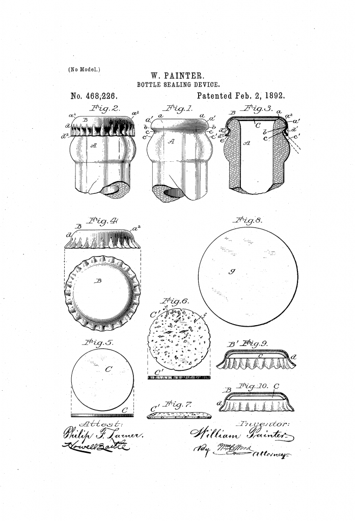
Painter used figures to illustrate each part of the bottle-sealing device: a metal cap, a sealing disk, and the bottle itself before and after they were sealed, which made comprehending his invention much easier and more interesting to look at. The metal cap was in the form of a flange with ridges at the bottom.  From the figures used, the metal cap was locked in place with the sealing disk underneath it, and the disk, at its edges, was compressed between the metal cap and the ring shaped bottle lip. Also, there was a figure of how the sealing disk looked like before and after it was compressed between the bottle head and the metal cap. As simple as it may sound on paper, Painter came across a few issues along the way to invent the bottle sealing device.

One was with the shape of the bottle that had a sharp, flat lip and a wide head. This shape increased the costs of making sealing disks as these disks had to be thick for such bottles. The wide head also gave more room for the gases in fizzy liquids to escape without properly sealing them. To counter this, Painter reshaped the bottle by making the lip of the bottle in a shape of a ring and making the head narrow, which allowed Painter to use a thinner sealing disk and keep the costs down as well. One can say Painter challenged the bottle manufacturers’ traditional bottle design to accommodate his invention. The plan to accommodate Painter’s invention was an issue in itself for the bottle manufacturers because the bottles had to be made according to certain specifications and had to be sealed in the right manner. This required enough force to seal the bottle. Painter responded by developing a “foot-powered crowner device” that made the sealing process efficient.

The second issue was the use of corks as a sealing disk. The problem was that high grade cork-wood was expensive. Painter’s solution was using a lower grade cork-wood. However, a lower grade cork-wood had “flinty” matter that was hard, and it could damage the metal cap with indentations when a high amount of pressure was applied to lock the caps on the bottle. Painter made alterations to the process of preparing corks by exerting a greater force to crush the “flinty” material. This made the sealing process easier by leaving no indentations on the bottle caps because the flinty material was crushed enough to make the finishing surface of the corks smooth.

The third issue was with the bottle sealing cap itself. High compressive forces were needed to seal the bottle, and it could neither be sealed nor opened by hand. A special device called the “bottle cap lifter”, later called bottle opener, was needed to open such bottles. Painter himself admits the disadvantage of sealing devices in his letter: “In as much as the application of my sealing caps involves powerful mechanism for compressing the disks and for bending or crimping the flanges of the caps into locking contact with bottles, it follows that considerable manual force must be applied for detaching the caps from the bottles.”[i] The design of the bottle opener used a sharp object that could slide between the bottom edge of the cap and the head of the bottle where force could be applied at various points to open the bottle with minimal effort. In 1894 Painter received a patent for the bottle opener and the combination of his inventions that meant fizzy drinks could be enjoyed at home with convenience.

William Painter, US468226A

The roadblocks that Painter encountered pushed him to come up with solutions to overcome the disadvantages in the design of his bottle-sealing device. A particularly interesting solution was the use of an adhesive which was “odorless, tasteless and practically insoluble” serving two purposes: to attach the sealing disk to the metal cap and to act as a protective layer from corrosion. While all this is easy to visualize today, as it’s very commonly seen, it was quite difficult to visualize this invention in 1891. This makes the figures used a valuable part of the patent description. They very accurately show the different aspects of packing such as the metal cap before and after being locked into the machine (figures 4 and 3), the sealing disk (figures 5 and 6), and the new bottle shape itself (figure 1 to 3).

The patent was awarded because it was radically new and very useful indeed.  It later helped the beverage industry grow into major brands such as Coca-Cola. This invention was not obvious because Painter used metal caps in combination with a cheap cork used as an effective sealant. The metal caps in question were not very thick and could’ve been damaged if the cheap corks were not processed properly.

Painter was inventive and bold as he went against the established methods of bottle manufacturers of having a sharp lip and a wide head. His methods were vindicated because the invention successfully sealed the fizzy liquid contents and led to a new standard in drink bottle design. It was this invention for which he attained widespread attention and became wealthy, which led to the formation of Crown Cork and Seal Company that exists even today. I must say very few people go against convention, and we should be glad that he did. No one enjoys a flat soda.

By Jash Shukla


[i] “William Painter.” Lemelson-MIT, lemelson.mit.edu/resources/william-painter. Accessed 6th February 2018.

Spring Type Bust Developer

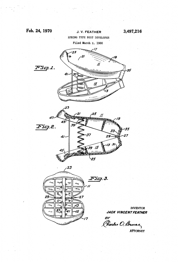
In the early 1950s, Jack and Eileen Feather opened a chain of gyms in California and Nevada targeting women who hoped to lose weight. The couple called the gyms “Eileen Feather Reducing Salons,” they branded Eileen herself as the “nation’s leading figure authority,” and their advertisements promised women they could achieve “Figure Perfection” in just thirty days.[i]  As the Feathers told it, when clients who were losing weight began to complain that they were also losing inches from their bustlines, Jack designed a bust enlarging exercise device. He named the device after novelist Jack London’s fictional character, Martin Eden, a self-taught writer striving for fame and recognition.[ii]

Thus began the Mark Eden bust developer, an odd-looking pink exercise device comprised of two hinged, clam-shaped hand grips kept apart by a high-tension spring. The device itself was less memorable than the advertisements, which appeared in mainstream women’s magazines, and featured large breasted white women in revealing clothing. The first advertisement for the Mark Eden bust developer appeared in March 1965 and offered women the possibility to “develop and beautify [their] bustline to its maximum degree or fullness ”in the privacy of their own homes.

Women who sent $9.95 to the Feathers received the pink clamshell exerciser and a booklet illustrated with pictures of the curvaceous model June Wilkinson, who was by then famous for her numerous Playboy spreads.

As soon as the Feathers began advertising the Mark Eden bust developer in nationally circulating women’s magazines they received thousands of orders. Just as quickly, the U.S. Post Office took legal action against the Feathers alleging that their bust developer was ineffective and its advertising was fraudulent. What followed was a 15-year battle between the Feathers and the Post Office.[iii]

In the midst of this battle, in 1966, Jack Feather applied for a patent for his exercise device, which was granted on February 24, 1970. The patent application described the equipment as “a new and novel exerciser for developing the female bust.” According to the application, this breast developer was an improvement over existing hand-operated exercisers because of its small size, light weight, and easy-to-grip shape which made it safer for women to use. Other hand-held exercise devices, he claimed, could easily fly out of women’s hands, leaving them “seriously bruised and injured,” and even exposing them to “the danger of breast cancer.”[iv]

Despite receiving a patent from the U.S. Patent Office, the Post Office held a total of three mail fraud hearings against the Mark Eden Corporation. The Post Office’s experts argued that strengthening a woman’s pectoral muscles could not change the actual size of her breasts. Meanwhile, the Feathers’ attorneys and expert witnesses denied this claim. Jack Feather himself stated that, “the development of the pectoral muscle has a profound effect on the appearance of the entire bustline. The breasts are lifted, firmed, the skin is toned, the whole bustline takes on a more rounded, lifted, youthful shapely appearance.”[v]

In 1966, while Jack Feather’s patent was still pending, the Post Office’s Judicial Officer deemed the Mark Eden ads fraudulent. In response, the Feathers sued and received a temporary restraining order preventing the Post Office from interfering with its mail. But in 1967, yet again, the Post Office began another proceeding against them. As the Feathers’ battle with the Post Office continued, other government agencies attempted to shut their corporation down.

The Food & Drug Administration, the Federal Trade Commission and various state agencies all investigated the Mark Eden manufacturers for fraud and false advertising. Each time a government agency tried to shut them down, though, the Feathers used the courts to mount a successful defense.

Finally, in 1982, a federal grand jury in San Francisco indicted the Feathers on mail-fraud charges, but the Feathers settled the suit out of court without admitting guilt. Under the agreement, the Post Office dropped the criminal proceedings, and Jack and Eileen Feather agreed to stop manufacturing and selling the Mark Eden Bust Developer, as well as various other products including the Mark II Bust Developer, the Astro Trimmer, the Sauna Belt Waistline Reducer, Vacu-Pants, Trim Jeans, and Dream Wrap. The Feathers agreed to pay the Post Office 1.1 million dollars and the government dismissed the indictment. By then, the Mark Eden breast developer had been in circulation nearly twenty years, and the Feathers had built a small fortune exploiting women’s dissatisfaction with their bodies.

By Gillian Frank, Lauren Gutterman, Rebecca L Davis, Saniya Lee Ghanoui, Devin McGeehan Muchmore


You can learn more about the Mark Eden system and its reception at Sexing History, a podcast about how the history of sexuality shapes our present.

Sexing History podcast

iTunes, https://itunes.apple.com/us/podcast/sexing-history/id1264132399

Feedburner, http://feeds.feedburner.com/SexingHistory

Stitcher, https://www.stitcher.com/podcast/sexing-history?refid=stpr


[i] See for example The Oakland Tribune, May 22, 1955 S13.

[ii] Cynthia Gorney, “The Rise & Fall of an Empire; Lean Times Hit The Fad That Swept America,” Washington Post, September 27, 1983, D1.

[iii] Mark Eden v. Lee, 433 F.2d 1077 (9th Cir. 1970); Eden v. C.I.R., 53 T.C.M. (CCH) 195 (T.C. 1987)

[iv] Grant US3497216A, February 24, 1970.

[v] Jack Feather, “Official Transcript of Proceedings before the Post Office Department,” in the Matter of: Mark Eden of San Francisco, Docket No. 2/204, March 18-22, 1968. NARAL San Francisco.


Solventless mixing process for coating pharmaceutical ingredients

Have you ever pondered why most pharmaceutical drugs have no taste? Or, if you do not swallow the tablet in a timely manner, an unpleasant taste forms in your mouth?

Pharmaceutical drugs have had plenty of problems. One notable conflict is the aversion toward the taste of the tablets. The pharmaceutical industry has tried to develop mechanisms to alleviate this problem such as increasing the speed of the tablets to dissolve, using liquids and syrups, the usage of patches and gums, and lastly dissolving the tablets in liquid. Most of these methods ended in failure and disapproval from customers. Professor Rajesh N. Davé (of the New Jersey Institute of Technology Otto H. York Department of Chemical, Biological and Pharmaceutical Engineering) and two of his former graduate students, Daniel To and Maxx Capece, presented a solution with their 2015 patent “Solventless Mixing Process for Coating Pharmaceutical Ingredients.” This patent thoroughly explains the different techniques in coating a taste-masking tablet. The thought process for this patent is that children and adults refuse to take medicine and remedies due to the taste. It will be easier for patients to swallow or chew tablets when there isn’t any taste.

What ingredient does the unpleasant taste come from and what is the process of coating?

The undesirable taste of the tablet comes from an active pharmaceutical ingredient (API). To mask the taste, the mixing must occur in water soluble materials or swellable coating materials and water insoluble polymer particles. The six methods of coating are:

  1. Coating with fine wax particles using fluid energy milling
  2. Dry-coating core particles with distribution
  3. Mechanical dry coating of wax onto copper powder
  4. Coating process when ascorbic acid particles are pulverized and coated with wax
  5. Dry coating using polymer powders
  6. Dry coating solid dosage

What are some realizations of the Patent US9107851B2?

This invention is the use of mechanical dry process. The first step in the taste-masking process is mixing the API fine particles first with the soluble coating materials, then with water insoluble polymer particles. After the mixing and the coating is formed, the tablet must go through a mechanical stress of high temperature in which it develops a film. After that film is complete, the API is masked for approximately one minute before the coating dissolves in its entirety. The tablet size must be between 30μm and 2mm. The amount of coating depends on the size of the pill; larger tablets will need more soluble and insoluble materials than a smaller pill would.

A water swellable version contains characteristics in which the material absorbs the water and swells. The materials in the tablet include croscarmellose, crospovidone, and sodium starch glycolate. The median size must be in the range of 0.5μm to 20μm. The water soluble material must have a solubility of at the very least 50 mg/mL at 20 degrees Celsius with a neutral pH. Some examples of soluble materials are lactose, poly-ethylene oxide, and hydrophilic polymers. For the water- insoluble polymer, the median size for the particle size can range from 1μm to 20μm. For the material to deform in this polymer, the temperature must be elevated, it has to go under a great deal of mechanical stress, or a combination of both. Castor wax, polypropylene, and polyamide wax are insoluble materials.

What is the mixing process?

The mixing process is applied with mechanical stress for about 1 minute to 4 hours. The amount of mixing time depends on the coating process used and the machine in use for the mixing. One method of mixing can be carried out by high energy vibrations with an acceleration of 9.81 m/s^2. The intensity number must not be lower than 10 or exceed 100 and the API size cannot exceed 100μm. The particles in the soluble and polymer must collide at high velocity, causing the coating surface to deform the API, which will lead to continuous coating. Another mixing process is executed by acoustic mixing at a high-intensity, low frequency acoustic energy being transferred to a mixing chamber.

What is the last processing method?

The insoluble polymer must be distributed over the API via vibrating, impacting, and tumbling in a mill. The mixing must be at high energy but not too excessive for the polymers to break the host particle. The average size of the particles is no less than 95% of the original particle size. A reduction of the expected size can be a sign that the process was not conducted correctly and that the coating is not thoroughly spread. A well-coated tablet will feature the desired dissolution characteristics along with the API being restricted for at least 30 minutes.

The presence of media particles enhances the formations of the continuous polymer coating, which could possibly better mask the taste. The API size to the media particles size ratio has to be between 3:1 to 10:1.

How long does it take for the coating to dissolve entirely and the unpleasant taste to be revealed?

The dissolution tests have shown that after 1 minute of the tablet in one’s mouth, about 95% of the API ingredient is concealed, and there is still no taste. The drug coating is less than 0.01% of taste-release. For most methods of coating, a little less than 0.5% of the API element is released after 2 minutes of the tablet in one’s mouth. After 30 minutes with the tablet in mouth, 90% of the API element is released, the same as if the tablet had not been coated. If the methods stated above are not thoroughly conducted such as running out of coating or inadequate taste-masking, the water soluble coating will dissolve quickly which will lead to the API being revealed before expected. Another factor in which the API will be released before expected is when the particles for the water soluble and insoluble polymers are not close enough to react.

Outcome

In 2016, the inventors of this patent were awarded a Thomas Alva Edison Patent Award from the Research & Development Council of New Jersey.[i] The patent was licensed to a global health care company, which is attempting to bring this technology to market.

By Hakilah Hudson, Glenn Monroe, John Saviano


[i] Tracey Regan. “NJIT Engineers Win an Edison Patent Award for Technology that Masks the Taste of Bitter Drugs,” Innovations at NJIT. Nov. 4, 2016, http://www6.njit.edu/features/innovations/dave-edison-awards2.php


Improvised Explosive Device Detection/Destruction/Disablement

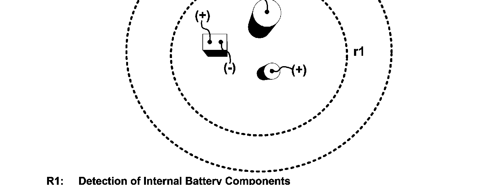
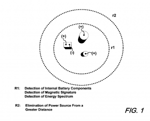
The U.S. patent system creates an environment which inspires inventors to create new or improve upon past inventions. This allows for the continuous improvement of various types of technologies. Additional influences may also be drawn from sources within a larger social context, as seen the efforts of Carlos M. Pereira, Hai-Long Nguyen, Edip Niver, Aladin H. Kamel, and Mohamed A. Salem, who were influenced by terrorist attacks which have been known to use improvised explosive devices (IED). IEDs are bombs which can be hidden in plain sight, as they can be integrated into unsuspecting, mundane objects, such as cars, computers, calculators, etc. This ambiguity and danger could be viewed as a catalyst for the need of a safe solution to handle these deadly bombs, resulting in U.S. Patent #7717023B2, “Improvised Explosive Device Detection/Destruction/Disablement.” The research behind this patent involved a collaboration between faculty and students at Stony Brook University, the U.S. Army, the New Jersey Institute of Technology, and Ain Shams University. Moreover, the funds contributed towards this invention were given by the U.S. government, indicating efforts to improve national security and assist military forces combating the use of IEDs today. The invention is designed to detect and identify IEDs within a radius of 50-100ft and can subsequently deactivate and/or destroy the explosive at a safe distance. Utilizing this technology can both improve our safety as well as take care of these disguised bombs without placing an individual in harm’s way.

U.S. Patent #7717023B2 allows for impressive integrated features in technology that was once not available. This patent has impacted the way the military can approach areas known to have IEDs in any given location. For example, instead of having to approach and search a dangerous area surrounded with hidden bombs, the military can now see if there are any IEDs in their area, and deactivate or safely detonate them without placing anyone’s life put in danger Any device that is integrated with this patent, while maintaining a satisfactory level of safety, can detect an IED using one or more methods. The methods include detecting internal battery components, magnetic signatures, chemical signatures, and any other high amounts of energy characteristics that may be present within IEDs. When an IED is detected, the device can then further characterize the IED in order to deactivate or safely destroy it by way of using a shape pulse charge (electromagnetic pulse) directed at the device in order to disrupt the bomb’s power source (battery) from a safe distance.

Carlos M. Pereira, Hai-Long Nguyen, Edip Niver, Aladin H. Kamel, Mohamed A. Salem, US Patent 7717023B2

The inventors have credited a number of other inventions prior to theirs, including U.S. Patent #6341551B1, “The Land Mine Hunter Technique,” which has the capability of detecting and neutralizing land mines for mine breaching and mine clearing; U.S. Patent #6825792B1, “Missile Detection and Neutralization System,” which can determine the precise launching point of ballistic missiles and has the ability to neutralize them as well; and finally, U.S. Patent #7071631B2, “Electromagnetic Pulse Device,” with the ability to create an electric discharge from a short circuit in a conductive coil in order to compress a magnetic field. Together these patents can be reflected in the creation of the Improvised Explosive Device Detection/Destruction/Disablement. The Land Mine Hunter Technique and the Missile Detection and Neutralization System both use wireless detection techniques for specific lethal weapons and explosives; along with the capability of deactivating them. The Electromagnetic Pulse Device brings the method of deactivation into a larger scale because it can deactivate any magnetic field, which can render any wirelessly connected bomb useless. Since IEDs are not necessarily land mines or missiles, and they can be hidden in plain sight while being connected wirelessly or with the use of motion detection, the creation of the Improvised Explosive Device Detection/Destruction/Disablement, has allowed for a rather graceful solution to a very dangerous weapons tactic.

U.S. Patent # 7717023 B2 has itself been cited by U.S. Patent #8490538, “System For Protecting Surfaces Against Explosions.” This invention can generate an explosive force intended to counteract an initial explosion by attenuating the shock wave and deflecting shrapnel. This patent is very helpful in that it provides a safety feature for the situation of a bomb that has already exploded by mitigating the damage it would have otherwise created without safe intervention. Due to the number of patents that have influenced one another involving explosives, solutions have been made for identifying a wide variety of hidden bombs as well a backup plan in case an unexpected bomb were to go off. When viewing the cited and referenced patents it became clear that this type of threat detection technology reflects the efforts of many to combat the danger of bomb threats, especially with pressure from typical terrorist attacks which have been known to use IEDs.

Since the Improvised Explosive Device Detection/Destruction/Disablement replaces the need for physical searching of IEDs (given that the device is within detectable range of said bombs), search dogs are also no longer necessary to combat IEDs. Without the need of search dogs, their lives can be spared as well. Not only that, but search dogs can be very costly for a method that only has a 75% success rate despite their heightened senses. It costs an estimated $4,000 to buy a dog trained to search bombs, and $35,000 to deploy them.[i] It is arguably much more efficient for a device that requires little to no risk of life to locate IEDs as well as disable or deactivate it.

Although the patent possess many advantages, it is still not perfect and cannot be used in all situations. The probability of the detection system malfunctioning is presently unknown, a matter which should not be taken lightly, as a defect in the system could easily result in the fatal encounter of a live IED. An additional concern is the invention’s limited detection radius, which only reaches up to 100 ft. The invention would be useless if it were to be integrated onto a drone where detection and deactivation of IEDs would be done with a much safer and more effective rate.

By Samantha Miccio, James Romano, Bryan Taveras


[i] Rick Atkinson, “There was a two year learning curve…and a lot of people died in those two years.” The Washington Post. Oct 1, 2007. Web. Nov 22, 2016. <http://www.washingtonpost.com/wp-dyn/content/article/2007/09/30/AR2007093001675.html?sid=ST2007092900754>

Composite Floor System Having Shear Force Transfer Member

There are many things that we take for granted every single day. The floor we walk on is one of those things. How many times have you thought about the floor underneath you? Probably not even once! But the use of flooring in buildings is not a simple task. An engineer must account for potential energy absorption, load carrying capacity, durability and stabilizing agents when designing a specific floor plan for any specific building. This job has gotten a lot easier thanks to Cheng-Tzu Thomas Hsu, Sun Punarai, and Pedro R. Munoz from the New Jersey Institute of Technology. Their patent, “Composite Floor System Having Shear Force Transfer Member” aids engineers when they lay down flooring in multifamily housing, commercial buildings, and even hospitals.

The late Dr. Cheng-Tzu Thomas Hsu, Professor in the Civil and Environmental Engineering Department at the New Jersey Institute of Technology, alongside his former Ph.D. students Dr. Sun Punarari and Dr. Pedro R. Munoz, were granted this patent in August of 2010. This patent would later be similar to other patents, such as the ones originating from Nucor Corporation (US Patent # US8636456B2) and patents by Urbantech Consulting Engineering (US Patent # US9518401B2), that deal with the shear strength of flooring projects.

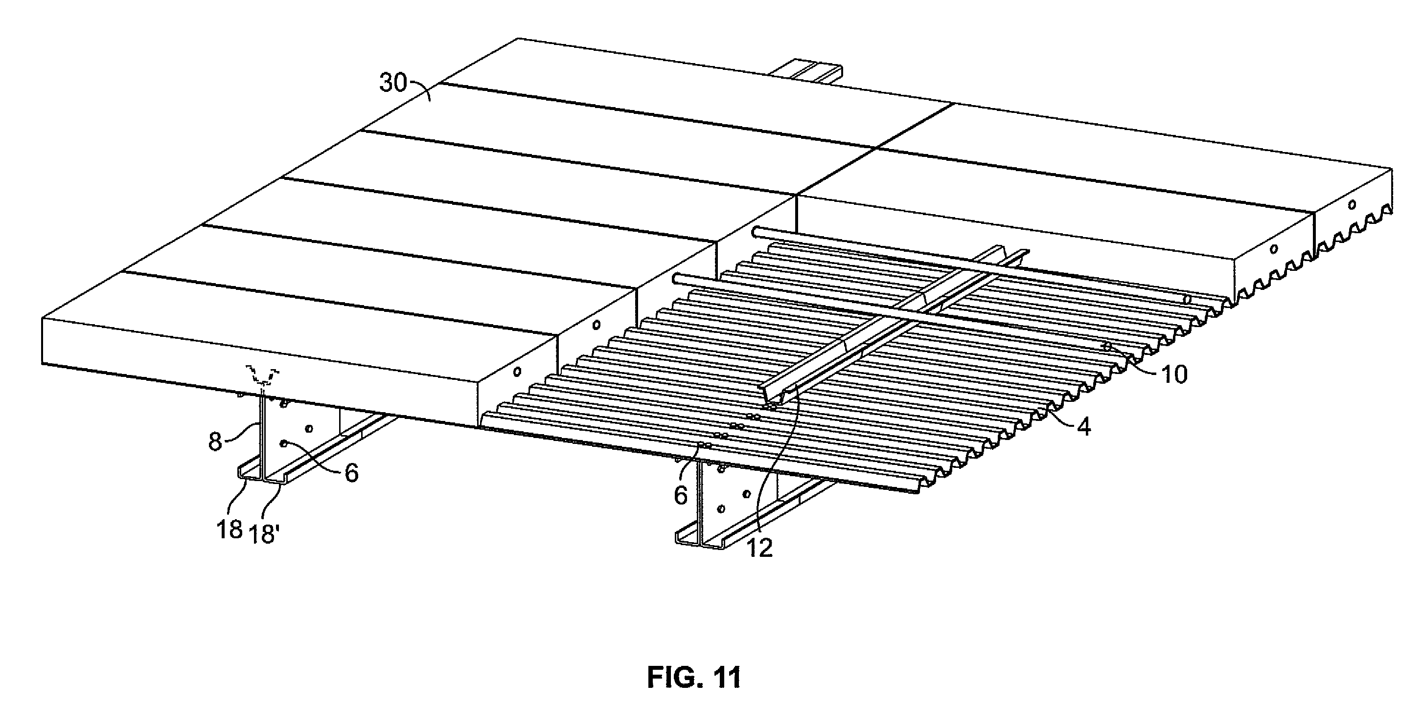
The common denominator amongst those three building types aforementioned is that they need tough flooring in order to withstand the day-to-day activities. Take a hospital for example; the flooring must be sturdy enough to withstand the weight heavy machinery, like an MRI machine PET and CT scanners, that are needed to make patients well. A “composite floor system” refers to a system that encompasses the use of multiple materials in the construction process of a floor system. In this specific patent, the composite floor system comprises of a slab, a deck material that is custom sized and shaped to support the slab, a support member attached to the deck material and a transfer member attached to both the slab and the deck. As you can see from the image, the slab and the deck are not simply placed on top of one another as most “non-composite” floor systems do. In this composite system, there is space in between the metal deck material and the actual flooring. This space, once embraced, will enable for an increase in the tensile strength which grants the floor the ability to carry much more weight.

Cheng-Tzu Thomas Hsu, Sun Punarai, Pedro R. Munoz, US Patent 7779590B2

This invention allows for more than just the ability of the floor to carry more weight. It grants engineers the capability of using lightweight materials that can easily be fabricated. These materials are incredibly easy to handle and transport, saving time and money all throughout a specific construction project. Moreover, this invention can minimize the need for expensive and sophisticated quality control measures that are needed to test a specific floor. Since this composite system can be put together off-site and then transported to the construction site, the floor system is capable of achieving the desired load capacity before even placed in the flooring of the building and thus saving massive amounts of time and money for construction workers.

“Composite Floor System Having Shear Force Transfer Member” has the capabilities of remodeling the process of construction across the spectrum. An increase in the desired weight carrying capacity of a floor can enable new types of architectural designs to lavish city streets. Most buildings today all look the same because they mainly follow the same concepts of building technologies. But with composite technology the potential of building marvelous architectural structures is a reality. If the central ideas behind a composite floor are implemented in walls and ceilings – which is currently in development and filed in the USPTO to be patented technology (see: US20140144091A1, “Composite wall panel, wall system and components thereof, and a method of construction thereof”) – structures will no longer have to be rectangular and a copy of the building next to it. Buildings can now be circular, triangular, hexagonal, etc. without giving up durability and stability.

The innovation of changing architectural designs is the fundamental contribution brought to society by this patent. Moreover, even though this particular patent is related to just the flooring system of construction, the focal point of the patent has the ability to flourish into something much larger than just flooring systems. A composite designed flooring system, with its light weight and durable characteristics can be used on transportation technologies such as airplanes and trains. Or used in elevators and moving walkways for the elderly. The potential uses of this technology could be seen in just about every imaginable structure in today’s society.

By Michael Tadros

Unauthorized User Prevention Device and Method (continuation)

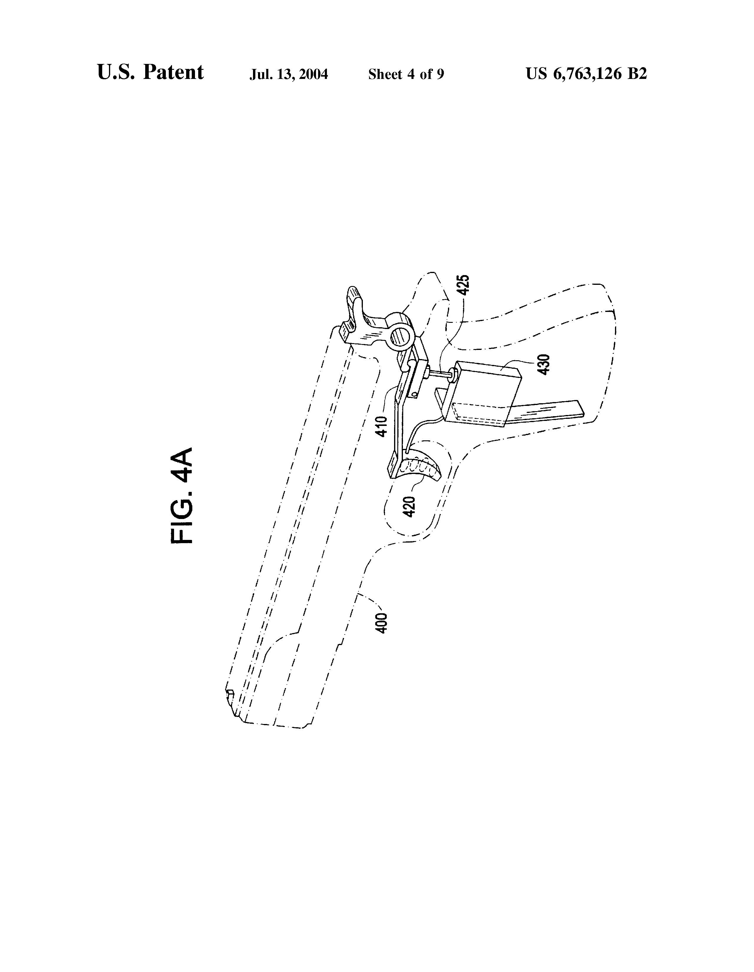
Gun safety in our nation, and especially around our children, has become a hot topic to discuss – not only in the media and in news outlets, but in the classroom and in technological labs. Thanks to a patented technology by Dr. Michael Recce, you can put down your gun at home with the peace of mind knowing your 10-year-old won’t be able to shoot it.

Recce’s 2004 patent, “Unauthorized User Prevention Device and Method”, does exactly that. By adding pressure sensitive sensors in the handle of the gun, unauthorized users will not be able to discharge the weapon without matching the same amount of pressure exhibited by the authorized user. When a user purchases one of these guns, he or she must first register or “save” the owner’s pressure profile into the sensor on the gun. When it comes time to shoot the gun, only the same pressure matching the profile saved will unlock the firearm allowing the weapon to discharge. Visualize this technology as a high tech bike lock. When you lock your bike, only the person knowing the code to the lock will be able to unlock the bike and ride away with it. In Recce’s technology, the code to unlock the firearm is not numbers or letters, but the biometric pressure profile of each individual person.

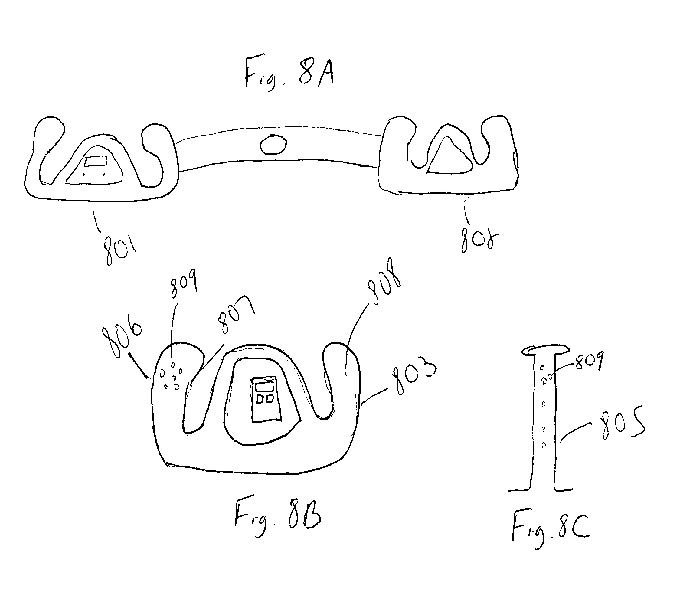
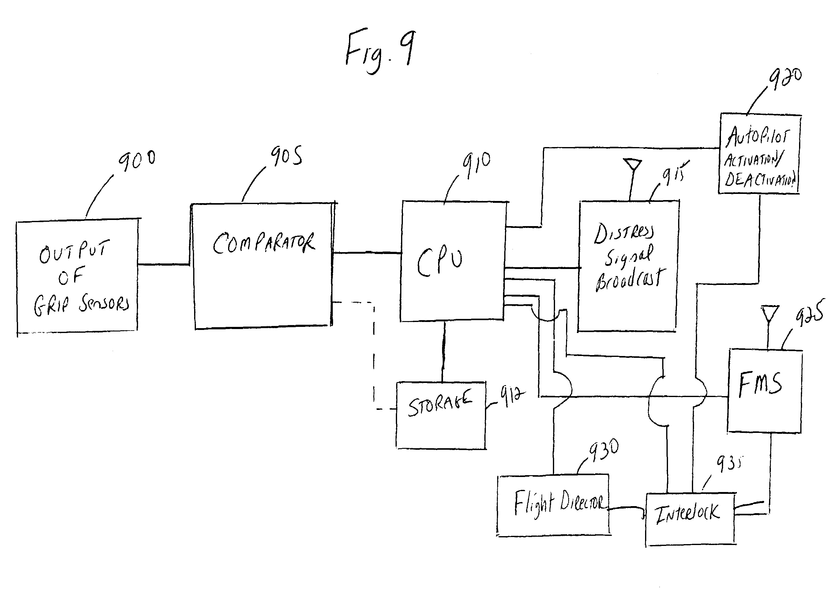
Recce’s invention didn’t gain much traction in a commercial perspective. That being said, it did give the idea of adding pressure sensors to other useful technologies such as cars, trains and airplanes. (He received a patent for use of this technology on airplanes in 2006, US7155034 B1). In most trains today, the lever used to control the accelerator, commonly referred to as a “dead man’s switch” is operated with an ideology that is similar to Recce’s pressure sensor. Once the conductor releases his hand of the accelerator, and essentially releasing the pressure from the switch, the train forces itself to apply the break. Recce applied for a similar patent to this specific one that will allow his technology to be implemented on commercial passenger airplanes (granted in 2006: US7155034, “Authorized Personnel Biometric Detection System Preventing Unauthorized Use Of Aircraft And Other Potentially Dangerous Instruments”). Similar to the handgun, once an unauthorized user gets control of the airplane, the aircraft will contact ground control and the unauthorized user will not be able to control the airplane.

This technology can be incredibly useful. It ensures the safety of children and other individuals who are unauthorized to handle your gun. Imagine a struggle with a police officer and a criminal where the criminal overpowers the officer and is able to take his gun. This technology will make it impossible for that criminal to be able to discharge the weapon – effectively saving multiple lives.

This technology does, however, have its flaws. As previously mentioned, the sensor operates with the pressure exerted on it by a user. There can be multiple scenarios where the authorized user of the handgun exerts too much pressure, or maybe even not enough pressure, and not have the handgun discharge. This fault can be a matter of life or death in many scenarios. People fear that there really is no way of being 100% certain that the gun will discharge when you absolutely need it to. In some cases, the authorized user might be nervous or scared and grip the gun extra tight and cause the sensor to not pick up the correct amount of pressure needed to unlock it.

Without any state supporting the development and implementation of these “smart” guns, it is up to the user to make the conscious decision to opt for a “smart” gun. However, even that is easier said than done. At present, these “smart” guns remain unavailable in gun stores and face vocal criticism from the NRA. These are among some of the issues which have contributed to the lack of commercial success for Recce’s patent. With further development funding, however, NJIT’s Senior Vice President for Research and Development, Donald Sebastian, argues that Recce’s gun could be available for market within two years.[i]

By Jacqueline Tanis, Michael Tadros, Rohit Saraiya


[i] Matt Giles, “Can A Smarter Gun Prevent A Massacre?” Popular Science, Dec. 4, 2015. http://www.popsci.com/can-a-gun-prevent-a-massacre

Authorized Personnel Biometric Detection System Preventing Unauthorized Use of Aircraft and Other Potentially Dangerous Instruments

The patent for an unauthorized device having the capabilities of being locked through biometric technology was created by Dr. Michael Recce. In 2003, he received patents on pressure/fingerprint scanners. Prior, there was nothing quite like it. The designs were an entirely new idea, something that was almost movie-like in conception. At the time of his patent, there were only physical locks to the cockpit, and safes and locked holsters for guns. There was no way of authorizing a designated user while simultaneously denying access to other persons. The process that he invented is capable of measuring multiple sensors simultaneously every 10 milliseconds. This was the answer to the problem that the market was having in regards to biometrics. Its usage is limitless and can be applied to anything that a human operates, whether it is found on a gun, an airplane, a boat, a power tool, or even construction equipment. The intended purpose of its creation was to prevent malicious use of objects, devices, or crafts. Should Recce’s invention achieve success and become widely utilized, it would result in a massive decrease in accidental and malicious deaths. This preventive measure is said to be the inventor’s chief motivation behind his work.

At the time, Recce was a professor of Information Systems at the New Jersey Institute of Technology. He recently held a Quantcast segment at IAB Engage, in 2013, discussing computer advertisement, specifically studying the way young people interpret ads and which part of the brain accepts the message of the ad. Recce currently holds five patents in three major areas: the Unauthorized User Prevention Device and Method, which is the idea that became his biometric technology; consumption history privacy, which is a way for internet advertisers to target people based on the search history while protecting the identity of the person; and assessment of risk associated with doing business with a party. One may wonder what in particular motivated the inventor’s interest in biometrics. As an owner of multiple guns, Recce was aware of the danger and peril that could befall someone when an unauthorized person takes hold of a firearm. Concerned about the safety of Americans, he created the iGun, which utilizes biometric technology to identify the user of a firearm by the signature grip and hand print. This same concern for safety led him to expand his contributions in this technology to door handles for households, industrial buildings, offices, and vehicles, as well as car keys, ignition starters for vehicles, steering wheels for cars and aircraft, and the joy-stick on an aircraft.[i]

Michael Recce, US Patent 7155034B1

US7155034 is a continuation of prior fingerprint scanning technologies, arguably combining pre-existing methods into one. Recce’s patent cites twenty-six patents. Among them are US 3939679, “Safety System,” a remote-controlled safety mechanism; US 8172675 B2, “Personalization Using a Hand-Pressure Signature,” the memory storing device to record the pressure applied to it; US 9341424 B2, “Firearm Locking Assembly,” a locking mechanism used to prevent any use of the item (in this case, a firearm, joystick, door handle, etc.); and US 20060025900 A1, “Apparatus, System and Method for Aircraft Security and anti-Hijacking Intervention,” a prevention to keep unauthorized pilots from manning an aircraft any kind. Recce’s patent continues the creations and inventions that use fingerprint-matching technology, by uniting the three components of a form of ultrasound, silicon, and optical technology for the Authorized Personnel Biometric Detection System Preventing Unauthorized Use of Aircraft and Other Potentially Dangerous Instruments.

Other inventors have also drawn upon Recce’s work, in biometrics and safety technologies. Patents which cite his include: US 7406368 B2, “Apparatus, System and Method for Aircraft Security and anti-Hijacking Intervention;”  US 8172675 B2, “Personalization Using a Hand-Pressure Signature;” U. S. Patent #8762734 B2, “Biometric pressure grip;” US 8902044 B2, “Biometric control system and method for machinery;” US 9341424 B2, “Firearm locking assembly ;“ US 20060025900 A1, “Apparatus, System and Method for Aircraft Security and anti-Hijacking Intervention;” US 20090002161 A1, “Security System for Motorcycle Crash Helmet; ” and US 20140366714 A1, “Roman Shield Armored Vehicle (RSAV).”

The firearm is considered by many to be the most obvious and direct application of biometric detection safety systems due to its popularity among the American people: a staple instrument in the work of law enforcement and military professionals, and commonly used by the American public. Firearms are capable of causing deliberate and accidental harm in the hands of secondary users. Unfortunately, we experience both ends of that spectrum as well as everything in between. The airplane was never viewed in the same light as a gun. Mainly because they were seldom used to cause harm to others. The events of September 11th forced the United States to accept the transportation industry as a possible medium of terrorism.

It became apparent that Recce’s patent for firearm biometrics could be applied in areas not involving firearms, such as the transportation industry. Plane joysticks, tractor trailer steering wheels, and cruise ship helms could be protected courtesy of Recce’s biometric detection technology in order to prevent, or at least deter, terrorists from using these vessels to bring harm to others. This patent in particular is an example of how certain events in history, although sometimes tragic, spark innovation and creative thinking to better safeguard the public in the future. Much like the sinking of the HMS Titanic alerting the world to the need of maritime safety improvements, the terrorist attacks committed on the United States motivated inventors to create better technology to ensure the safety of the American people. It is this very thought process that fostered some of the most significant technological contributions of our day, notably, the biometric detection system patented through US7155034.

Michael Recce, US Patent 7155034B1

The invention process by its very nature is a scientific process that builds upon previous ideas of inventors passed. Whether changing the application of an invention or modifying it to meet current expectations of that product, technology is constantly changing to meet the needs of society. As is the case with these biometrics, which were initially intended for firearm safety and were later adapted to be applied to airplanes and other vessels.

By Naomi Segura, Brian Lallo, Robert Fullagar


[i] Giles, Matt, “Can A Smarter Gun Prevent a Massacre?” Popular Science, Popular Science. 04 Dec. 2015. Web. 06 Dec. 2016.